VLAN Segmentation on pfSense: Guest & IoT Networks
Split one flat LAN into three isolated networks — trusted LAN, guest Wi-Fi, and IoT — each on its own VLAN and subnet, with firewall rules that actually enforce the isolation rather than just labeling it. Covers renumbering off the default 192.168.1.1, creating the VLANs, and the specific allow/block rules each network needs.
Why segment at all
A single flat network means every device — laptops, phones, guest devices, smart plugs, cameras, the TV — can see and reach every other device. That's fine until one of them shouldn't be trusted: a guest's phone with unknown malware, or an IoT device with a firmware vulnerability the manufacturer never patched (both a genuine, ongoing category of problem, not a hypothetical). Segmentation means a compromised or just poorly-secured device on the Guest or IoT network can't reach anything on the trusted LAN, because there's no route there to begin with — not "we trust it not to," but "the firewall doesn't permit it."
Why move off 192.168.1.1 first
If you're already renumbering for VLANs, this is the moment to also drop the default 192.168.1.0/24 LAN — two independent reasons this matters, not just tidiness:
- Every consumer router ships with this range. Automated scanning tools, malware, and browser-based CSRF/DNS-rebinding attacks that try to reach "the router" often just guess
192.168.1.1outright, since it's correct often enough to be worth trying first. A non-default LAN isn't invulnerable, but it's not the first guess. - It collides with almost everything else. If you ever connect to another network on this same range — a VPN to a client site, a coffee shop, another location in a multi-site setup — a
192.168.1.0/24LAN can't be reliably routed alongside another192.168.1.0/24network. Picking something less common avoids that collision before it happens.
This guide renumbers LAN to 10.20.30.0/24 — a private range that's just as valid as 192.168.x.x but far less commonly used by default, so it doesn't collide with the networks you're most likely to encounter elsewhere.
Architecture
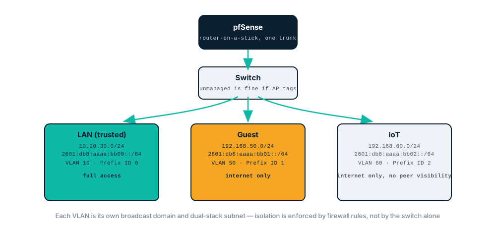
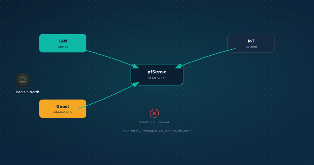
pfSense runs "router-on-a-stick" — one physical trunk port carrying all three VLANs tagged, with pfSense doing the routing and firewalling between them. The switch in between (managed or not — see Prerequisites) just passes tagged traffic; it doesn't enforce any isolation itself. All the actual separation happens in pfSense's firewall rules, covered below.
Prerequisites
- A VLAN-capable access point (for the wireless side — Guest and IoT SSIDs mapped to their VLANs) — most "prosumer" APs (Ubiquiti, TP-Link Omada, etc.) support this; built-in ISP router Wi-Fi generally does not
- A managed switch only if wired devices need VLAN assignment by port — an unmanaged switch passes 802.1Q-tagged traffic through transparently and works fine between pfSense and a tagging-capable AP; a managed switch is only necessary if specific wired ports (not the AP) need to be assigned to specific VLANs
- 30–45 minutes, plus a period of testing before trusting the isolation is complete
Step 1: Renumber the existing LAN
Interfaces > LAN, change the IPv4 address from 192.168.1.1/24 to 10.20.30.1/24. Update the DHCP range under Services > DHCP Server > LAN to match (e.g. 10.20.30.100–10.20.30.200).
Existing devices will pick up the new range on their next DHCP renewal; anything with a static IP in the old range needs manual updating. This is a good moment to also move any DNS overrides or firewall rules that reference the old subnet literal — search for 192.168.1. across your rule set before moving on.
Step 2: Create the VLAN interfaces
Interfaces > Assignments > VLANs, add one entry per VLAN on the parent interface that connects to your switch's trunk port:
| VLAN | Tag | Purpose |
|---|---|---|
| Guest | 50 | Visitor Wi-Fi |
| IoT | 60 | Smart devices |
(LAN stays untagged/native on the trunk — a common default, though tagging it too is equally valid if your switch config prefers that.)
Assign each new VLAN as an interface (Interfaces > Assignments), then configure its address under Interfaces > [VLAN name]:
LAN (existing):  10.20.30.1/24
Guest:           192.168.50.1/24
IoT:             192.168.60.1/24
Three genuinely distinct subnets — no overlap, easy to eyeball in firewall rules and logs.
IPv6: one delegated /56 split by Prefix ID, not separate delegations
Unlike a multi-site setup where each location gets its own ISP delegation, everything here is behind one WAN connection — one delegated prefix, split into a /64 per VLAN using Track Interface and a distinct Prefix ID for each, exactly the pattern covered in the subnetting reference.
On each VLAN interface (Interfaces > [VLAN name]), set IPv6 Configuration Type to Track Interface, tracking WAN, with a unique Prefix ID:
LAN    (Prefix ID 0):  2601:db8:aaaa:bb00::/64
Guest  (Prefix ID 1):  2601:db8:aaaa:bb01::/64
IoT    (Prefix ID 2):  2601:db8:aaaa:bb02::/64
Requires a /60 or larger delegation from your ISP (16+ /64s available) — a /56 gives 256, comfortable headroom for VLANs plus any future ones. As covered in the multi-site guide, this delegation is very likely dynamic (DHCPv6-PD), not a fixed assignment — confirm what you actually have under Status > Interfaces > WAN before treating these as permanent.
Step 3: DHCP and Router Advertisements per VLAN
Services > DHCP Server, enable on both new interfaces:
Guest DHCP range:  192.168.50.100 – 192.168.50.200
IoT DHCP range:     192.168.60.100 – 192.168.60.200
Point DNS server on both scopes at pfSense's own resolver (that VLAN's own gateway IP) rather than a public resolver directly — keeps DNS handling consistent with the DNS over TLS setup if that's in place, and means per-VLAN DNS-based rules or overrides are possible later.
Services > DHCPv6 Server & RA, enable on each VLAN interface for the IPv6 side. Router Advertisements handle address assignment for most devices via SLAAC; DHCPv6 is optional on top of that if you want it. Set Router Advertisements mode to Assisted (SLAAC + DHCPv6 stateless, covers the widest range of client behavior) unless you have a specific reason to require full DHCPv6 (Managed mode) instead.
Step 4: Firewall rules — this is where isolation actually happens
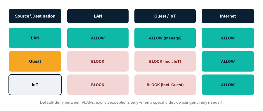
Creating a VLAN interface does not isolate anything by itself. Without explicit rules, pfSense's default behavior on a newly assigned interface is typically deny-all inbound — which blocks everything, including the internet — so the real work is writing rules that allow what should work while explicitly blocking what shouldn't.
Address Family: set every rule below to IPv4+IPv6, not just IPv4. pfSense supports this as a single combined option per rule — "LAN net," "Guest net," etc. as a Source or Destination automatically covers both the IPv4 subnet and IPv6 /64 assigned to that interface. One rule set, both protocols; no need to duplicate every rule for each protocol separately. (This differs from the WireGuard posts, where separate IPv4/IPv6 rules were needed for reasons specific to WireGuard's tunnel handling — plain interface-to-interface rules like these don't have that constraint.)
LAN rules (trusted — permissive)
Firewall > Rules > LAN: keep this close to default-open, since LAN is the trusted network:
| Action | Source | Destination | Notes |
|---|---|---|---|
| Pass | LAN net | any | Standard trusted-LAN rule, largely unchanged from before segmentation |
Guest rules (internet only, hard block to everything private)
Firewall > Rules > Guest, rules evaluated top to bottom — order matters:
| Order | Action | Source | Destination | Purpose |
|---|---|---|---|---|
| 1 | Block | Guest net | LAN net | Explicit block to trusted LAN |
| 2 | Block | Guest net | IoT net | Explicit block to IoT — guests shouldn't reach smart devices either |
| 3 | Block | Guest net | This Firewall | Block access to pfSense's own GUI/services from Guest |
| 4 | Pass | Guest net | any | Allow everything else (i.e., the internet) |
The block rules must come before the pass-any rule — pfSense evaluates top to bottom and stops at the first match, so a permissive rule placed above the blocks would make them meaningless.
IoT rules (internet only, no lateral visibility)
Firewall > Rules > IoT, same pattern, mirrored:
| Order | Action | Source | Destination | Purpose |
|---|---|---|---|---|
| 1 | Block | IoT net | LAN net | Block access to trusted LAN |
| 2 | Block | IoT net | Guest net | Block access to Guest |
| 3 | Block | IoT net | This Firewall | Block pfSense GUI/services access |
| 4 | Pass | IoT net | any | Allow internet |
Scoped exceptions, if something genuinely needs one
Some IoT devices (smart speakers with local control apps, some camera systems) work better — or only work — with a path back to a controller on the trusted LAN. If that's a real requirement rather than a "just in case," add a narrow exception above the relevant block rule, scoped to specific hosts and ports rather than opening the whole IoT-to-LAN path:
| Order | Action | Source | Destination | Port | Purpose |
|---|---|---|---|---|---|
| 1 | Pass | 192.168.60.20 (specific device) |
10.20.30.15 (specific controller) |
vendor-specified | Narrow, documented exception |
| 2 | Block | IoT net | LAN net | any | General block, unchanged |
Add matching IPv6 entries the same way if the specific devices have stable IPv6 addresses worth targeting (e.g., a DHCPv6 static mapping) — otherwise this exception can stay IPv4-only if the device or controller doesn't use IPv6 for local traffic anyway.
Same least-privilege principle as scoping firewall rules in the multi-site VPN guide — a specific host-to-host, port-scoped exception rather than reopening the whole subnet-to-subnet path for one device's convenience.
One layering note if you also run an overlay VPN: tailnet ACLs and pf rules are independent. A permissive ACL doesn't open a pf rule, and a pf block doesn't stop a tailnet peer that a rule elsewhere already permitted — so a device reachable over the tailnet can bypass assumptions built into the VLAN rules above. Tailscale vs. WireGuard on pfSense covers how the two interact.
Step 5: Test the isolation actually holds
Don't assume the rules work as written — confirm:
- From a device on Guest, try to reach something on LAN (e.g., ping the LAN gateway
10.20.30.1, or try reaching a LAN device's IP directly) — should fail. Repeat over IPv6 (ping the LAN gateway's IPv6 address) — a rule that only blocks IPv4 while leaving IPv6 open is a real, easy-to-miss gap - From a device on IoT, try the same against both LAN and Guest, both protocols — should fail every direction
- From LAN, confirm you can still reach devices on Guest and IoT if that's intended for management purposes (or confirm you can't, if LAN's rule was scoped narrower than "any")
- Confirm internet access works from all three networks, both protocols — a common mistake is a block rule ordered above the pass-any rule, which would also break legitimate internet access, not just cross-VLAN traffic
Extra credit: cross-VLAN Chromecast and AirPlay discovery (optional)
This is an optional addition, not required for segmentation itself to work. The moment IoT gets its own VLAN, Chromecast/AirPlay/HomeKit discovery from LAN devices typically breaks — worth expecting, not a sign something went wrong. Casting and discovery both rely on mDNS (multicast DNS), and multicast traffic doesn't cross VLAN boundaries by default — a VLAN is its own broadcast domain, and the isolation rules from Step 4 block the unicast fallback too. A phone on LAN can no longer see a Chromecast sitting on IoT.
Install Avahi: System > Package Manager > Available Packages, search "Avahi," install. This adds an mDNS reflector — it listens for mDNS traffic on selected interfaces and re-broadcasts it to the others, letting discovery work across the VLAN boundary without collapsing the boundary itself.
Configure it: Services > Avahi. Select the interfaces to reflect between — typically LAN and IoT — and enable the reflector checkbox. Restart the service after saving.
Scope it with reflection filtering, not "reflect everything." Avahi defaults to reflecting all mDNS service types if left unrestricted, which is broader than most setups actually need. Under the reflection filtering section, list only the specific service types in use (_googlecast._tcp, _airplay._tcp, _hap._tcp for HomeKit, etc.) rather than leaving it wide open — same least-privilege reasoning as everywhere else in this guide, just applied to service discovery instead of IP traffic.
A firewall exception is still required. Avahi needs mDNS traffic (UDP 5353, multicast address 224.0.0.251) to actually reach pfSense from IoT — but Step 4's IoT rules explicitly block traffic to "This Firewall." Add a narrow exception above that block rule:
| Order | Action | Source | Destination | Protocol | Port | Purpose |
|---|---|---|---|---|---|---|
| 1 | Pass | IoT net | This Firewall | UDP | 5353 | Allow mDNS to reach the Avahi reflector |
| 2 | Block | IoT net | This Firewall | any | any | General block, unchanged |
Guest generally shouldn't get this. Reflecting LAN and IoT together makes sense — you likely want to cast to your own devices. Including Guest in the reflection means visitor devices can discover (and potentially cast to) household Chromecasts and speakers, which is usually not the intent. Leave Guest out of the Avahi interface list unless that's specifically wanted.
If discovery still doesn't work after this: check the access point's own settings — many APs (Ubiquiti and others) have a "block WLAN-to-WLAN multicast/broadcast" toggle enabled by default for security, which silently defeats Avahi's reflection even when pfSense is configured correctly. This needs to be disabled for the SSIDs involved.
For actual screen/tab casting, not just app-based casting, some Chromecast use cases need more than discovery — mirroring a phone screen or browser tab requires the casting device to reach the Chromecast directly over TCP 5556 and 5558. If that's needed, add a scoped pass rule on the LAN (or wherever the casting device lives) allowing TCP 5556/5558 to the specific Chromecast's IP, rather than opening those ports broadly.
FAQ: VLAN Segmentation on pfSense
Does creating a VLAN automatically isolate it from my LAN?
No — a VLAN interface with no firewall rules typically defaults to blocking everything, including internet access. Isolation from other VLANs specifically requires explicit block rules; it doesn't happen automatically just because traffic is on a different VLAN.
Can Guest and IoT devices see each other?
Not with the rules in this guide — both networks explicitly block reaching each other, not just LAN. Two unrelated guest devices, or two IoT devices from different vendors, generally have no reason to talk to each other either.
Do I need a managed switch for this?
Not necessarily. VLAN tagging can happen entirely at the AP (multiple SSIDs, each mapped to a VLAN) — an unmanaged switch passes 802.1Q-tagged frames through without needing to understand them, since it just forwards Ethernet frames regardless of the tag. A managed switch is only required if specific wired ports need individual VLAN assignment — e.g., a wired IoT camera plugged into a specific port that should land on the IoT VLAN without an AP in the picture.
Why 10.20.30.0/24 for LAN instead of another 192.168.x.x range?
Any non-default private range works — the point is just avoiding the specific 192.168.1.0/24 default, not a 10.x vs 192.168.x preference. 10.20.30.0/24 is used here partly for visual distinction from the Guest/IoT examples in this guide's tables.
Should IoT devices be able to reach the internet at all?
Generally yes, for most consumer smart devices (firmware updates, cloud-dependent features) — full internet blocking is a separate, stricter posture some setups use, but isn't what this guide builds. If a specific device doesn't need internet access, blocking it entirely (rather than just LAN access) is a reasonable narrower rule for that device specifically.
Does this work with IPv6, or just IPv4?
Both — each VLAN gets its own /64 carved out of your single WAN delegation via Track Interface and a distinct Prefix ID (same pattern as the subnetting reference), and firewall rules set to Address Family "IPv4+IPv6" cover both protocols in one rule. The one thing worth double-checking specifically: a rule that blocks IPv4 but was accidentally left IPv4-only leaves IPv6 traffic between VLANs completely unblocked — test both protocols separately, not just IPv4.
Why did my Chromecast/AirPlay stop working after adding VLANs?
Expected, not a bug — mDNS (the discovery protocol both rely on) is multicast, and multicast doesn't cross VLAN boundaries by default. See the Avahi section above to restore cross-VLAN discovery deliberately, rather than undoing the segmentation to fix it.
Related reading
- Multi-Site VPN on pfSense: Connect Multiple Locations with WireGuard
- DNS over TLS on pfSense: Encrypt Unbound's Upstream Queries
- IPv6 Subnetting Guide: CIDR Prefixes & Usable Ranges
Recap
- A flat network means one compromised device can reach everything else — segmentation removes the route, not just the trust
- Move off
192.168.1.0/24for LAN while renumbering anyway — it's both the most commonly guessed default and the most likely to collide with other networks later - Router-on-a-stick: one trunk, pfSense handles routing/firewalling, the switch just passes tagged traffic
- Creating a VLAN interface doesn't isolate anything by itself — explicit block rules do, and rule order matters (blocks above the pass-any rule)
- Guest and IoT both get: block to LAN, block to each other, block to pfSense itself, then allow internet
- IPv6 rides alongside IPv4 throughout — one delegated prefix split by Prefix ID per VLAN, and rules set to Address Family "IPv4+IPv6" cover both in a single rule
- Scoped, host-and-port-specific exceptions beat reopening a whole subnet-to-subnet path for one device
- Test the isolation directly, over both protocols, rather than assuming the rules did what was intended
- Optional: Avahi restores cross-VLAN Chromecast/AirPlay discovery (mDNS doesn't cross VLANs by default) — scope it to specific service types and specific VLANs, not "reflect everything to everywhere"