Multi-Site VPN on pfSense: Connect Multiple Locations with WireGuard (No Vendor Fees)
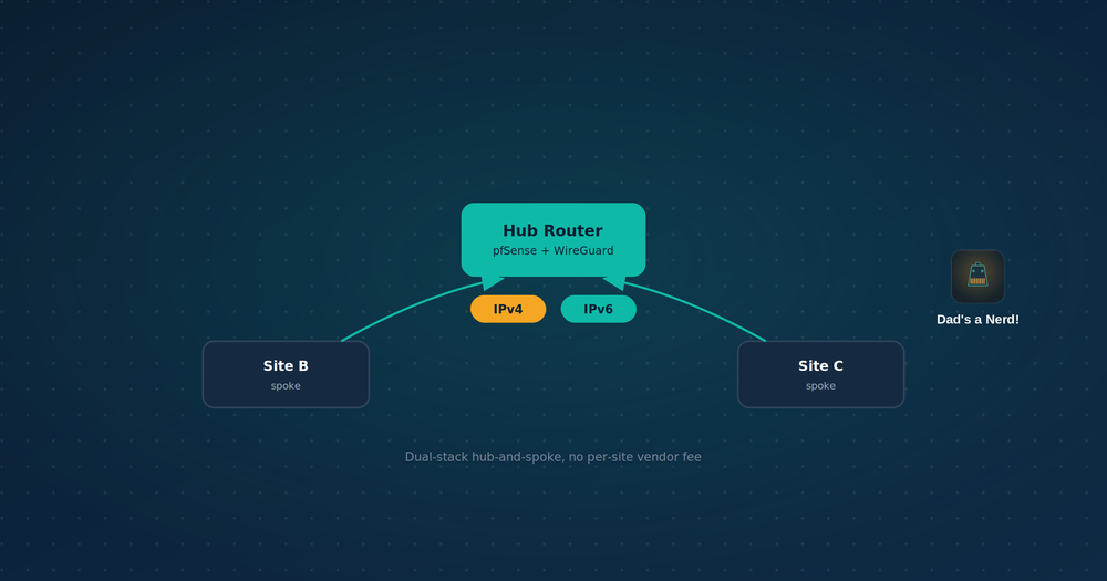
Connects multiple pfSense-routed locations into one routed, dual-stack (IPv4 + IPv6) network using WireGuard — a self-hosted multi-site VPN on pfSense in a hub-and-spoke topology. No NAT, no per-site static IP requirement, no recurring vendor fee.
Terminology note: the underlying technique here is a site-to-site VPN — a permanent, routed tunnel connecting two networks. "Multi-site" just means using that same technique more than once: a hub site runs a separate site-to-site tunnel to each additional location. Two sites is the base case (one tunnel, one peer on each end); three or more is that same setup repeated, with the hub acting as the common point. Nothing about the core configuration changes as sites are added — Step 2 through Step 5 are simply repeated per additional spoke.
This guide covers the full setup: non-overlapping subnet planning across sites, tunnel and peer configuration, the static routes both directions require, and firewall rules scoped to least privilege rather than a wide-open LAN-to-LAN allow. Worked example throughout uses three locations (one hub, two spokes) with real IPv4 and IPv6 addressing, but the same steps apply to two sites or ten. If you've only ever set up a single WireGuard tunnel to a phone or laptop, this is a different configuration — it connects whole networks to each other permanently, not a device to a network on demand — and the comparison table below covers exactly what changes.
When to use this vs. remote access
| Remote access (previous guide) | Site-to-site (this guide) | |
|---|---|---|
| Connects | A device to a network | Two or more entire networks to each other |
| Endpoint | Dynamic — client roams | Only the hub needs one — spokes work like remote-access clients |
| Peer count | One per device | One per site |
| NAT | Yes, for full-tunnel clients | No — full routing both directions |
| AllowedIPs | Scoped to the client or 0.0.0.0/0 |
Scoped to the other site's LAN (or specific hosts — see Step 3) |
| Runs on | pfSense as server, phone/laptop as client | pfSense on both ends |
Use case
Multi-location organizations — a business with two offices, a fire department with several stations, a club with multiple halls — often run systems that need to reach every location: key-card access control, a shared file server, VoIP. Vendor-hosted networking for this is commonly billed per-site, monthly. A self-hosted multi-site VPN does the same job for the cost of the hardware and internet connection already in place.
Per-site DDNS/static-IP fees are avoided too — see Step 3: only the hub needs a discoverable address.
Architecture
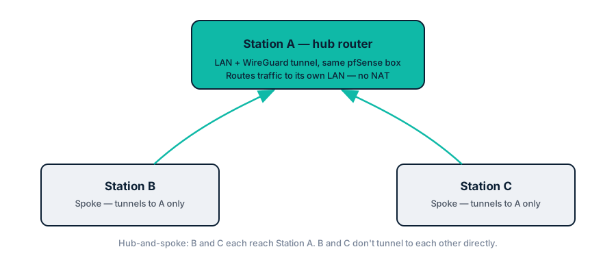
Station A is the hub. B and C tunnel to A only — not to each other. Each spoke's reader talks to the panel/server at A. A routes and firewalls that traffic; B and C never need a direct path to each other for this use case.
If two spokes do need to reach each other directly (not just both reaching the hub), that's a different, additional configuration: each spoke's AllowedIPs for its hub peer would need to include the other spoke's LAN too, plus a static route at each spoke pointing the other spoke's subnet through the hub gateway, plus a firewall rule at the hub permitting that specific spoke-to-spoke traffic on its own tunnel interface. None of that is covered here, since the worked example (readers reporting to one central panel) doesn't need it — worth checking whether your own setup does before assuming it's needed, since many hub-centric systems (key-card, file-server, VoIP) only ever talk to the central server, not to each other. Full mesh (below) is the cleaner answer if genuine spoke-to-spoke reachability turns out to be a real requirement, rather than bolting it onto hub-and-spoke.
Prerequisites
- pfSense + WireGuard package at every site
- Public IPv4 (static or DDNS) at the hub only
- Non-overlapping IPv4 LAN subnets at every site (see Step 1)
- A dedicated, unused subnet for the tunnel transport
- Optional: an IPv6 delegation per site (see the subnetting reference) — this guide is dual-stack throughout, but works IPv4-only if a site lacks IPv6
Step 1: Addressing plan
LAN subnets — must not overlap
Station A (hub):  192.168.10.0/24
Station B:        192.168.20.0/24
Station C:        192.168.30.0/24
Two sites both on 192.168.1.0/24 (the default on most consumer routers) cannot be routed between — there's no way to distinguish the two networks. Renumber before doing anything else.
Renumbering isn't the only way out, though it is the cleanest. Tailscale handles colliding ranges with 4via6, mapping each site's identical subnet into a distinct synthetic IPv6 route so both stay reachable without touching either site's addressing. Worth knowing before you renumber a live network — Tailscale vs. WireGuard on pfSense covers how it works and what the overlay costs you elsewhere.
IPv6 LAN — overlap is not a concern
Station A (hub):  2601:db8:aaaa:10::/64
Station B:        2603:1020:bbbb:20::/64
Station C:        2600:4040:cccc:30::/64
Each site's ISP delegates a globally unique prefix. Cross-site collision doesn't happen by construction — no planning required beyond not overlapping a site's own internal delegation (see the subnetting reference).
These are almost certainly not static assignments. Most residential and small-business connections get their IPv6 prefix via DHCPv6-PD (prefix delegation) from the ISP, with the LAN itself using SLAAC to hand out host addresses within it — not a fixed block you request once and keep. In practice a delegated prefix often stays the same for long stretches (sometimes indefinitely, depending on the ISP), but it's not guaranteed the way a manually assigned static IPv4 is. Confirm what each site actually has under Status > Interfaces > WAN before treating the addresses above as fixed, and if a prefix does change, everything referencing the old one — WireGuard AllowedIPs, static routes, firewall rules — needs updating to match. This is the same instability the remote-access guide's DDNS section exists to handle for the tunnel Endpoint; it's worth keeping in mind here too, just applied to LAN prefixes instead of a WAN address.
Transport network — dedicated, not carved from any LAN
IPv4: 172.16.99.0/29
IPv6: fd00:99::/64 (ULA)
Station A (hub):   172.16.99.1  /  fd00:99::1
Station B:         172.16.99.2  /  fd00:99::2
Station C:         172.16.99.3  /  fd00:99::3
A /29 covers hub + 5 spokes. Use a range unlikely to exist anywhere else (172.16.x.x, not 192.168.x.x). For IPv6, a ULA works since this traffic never needs to be globally routable. /127 per-link is the more "correct" choice at larger scale — see the subnetting reference.
Step 2: Create the tunnel at each site
VPN > WireGuard > Tunnels > Add Tunnel, on Station A:
- Description:
wg_hub - Listen Port:
51820 - Interface Keys: generate
- Address Configuration:
172.16.99.1/29andfd00:99::1/64
Repeat on B and C with their own transport addresses and their own keypair. Assign each as an interface (Interfaces > Assignments).
Step 3: Peers — only the hub needs a static Endpoint
Spokes connect outward to the hub, the same way a remote-access client connects to its server. They never need a discoverable address.
On Station B — peer for Station A:
| Field | Value |
|---|---|
| Public Key | Station A's tunnel public key |
| Allowed IPs | 172.16.99.1/32, fd00:99::1/128, 192.168.10.0/24, 2601:db8:aaaa:10::/64 |
| Dynamic Endpoint | Unchecked |
| Endpoint | Station A's public IP or DDNS hostname, port 51820 |
| Persistent Keepalive | 25 — keeps NAT/firewall state alive on B's side so the hub can reach back |
On Station C: mirror B's config, pointed at A.
On Station A (hub) — peer for Station B:
| Field | Value |
|---|---|
| Public Key | Station B's tunnel public key |
| Allowed IPs | 172.16.99.2/32, fd00:99::2/128, 192.168.20.0/24, 2603:1020:bbbb:20::/64 |
| Dynamic Endpoint | Checked — B has no fixed address; the hub accepts a handshake from wherever B currently is |
On Station A — add a second peer for Station C, same pattern.
This asymmetry (static Endpoint pointing at the hub from spokes, Dynamic Endpoint on the hub for spokes) is what lets spoke sites skip a static IP or DDNS entirely.
Unlike remote-access AllowedIPs (a peer's single address), a site-to-site peer's AllowedIPs covers that peer's entire LAN, since the traffic behind it is a whole network, not one device. Omit the IPv6 entries for a site without IPv6 — IPv4 works standalone.
Tighter scope option: if only specific hosts will ever communicate (e.g. one key-card reader talking to one panel), set AllowedIPs to those hosts' /32s and /128s instead of the full LAN. This is a WireGuard-layer restriction, not just a firewall rule — anything outside AllowedIPs isn't routable into the tunnel at all. Tradeoff: adding a new device later means editing AllowedIPs, not just adding a firewall rule. Use whole-subnet AllowedIPs when the link is meant to generally connect two networks; use host-scoped AllowedIPs when it exists for one known purpose only.
Step 4: Static routes — required both directions, both protocols
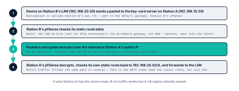
Create a gateway per tunnel peer first (System > Routing > Gateways), then add routes (System > Routing > Static Routes).
On Station B:
192.168.10.0/24→ gateway toward A2601:db8:aaaa:10::/64→ IPv6 gateway toward A
On Station C:
192.168.10.0/24and2601:db8:aaaa:10::/64→ gateway toward A
On Station A (hub):
192.168.20.0/24and2603:1020:bbbb:20::/64→ gateway toward B192.168.30.0/24and2600:4040:cccc:30::/64→ gateway toward C
A route only describes the outbound path. It says nothing about the return path, and an IPv4 route says nothing about IPv6. Missing the reverse-direction or the other-protocol route produces the classic symptom: traffic goes out, nothing comes back, tunnel looks broken but isn't.
Step 5: Firewall rules
WAN rule — hub only
Firewall > Rules > WAN, Station A only. Two rules:
| Field | IPv4 | IPv6 |
|---|---|---|
| Action | Pass | Pass |
| Address Family | IPv4 | IPv6 |
| Protocol | UDP | UDP |
| Source | Any | Any |
| Destination | This Firewall (self) | This Firewall (self) |
| Destination Port | 51820 | 51820 |
Spoke sites don't need this rule. A spoke always initiates the connection; pfSense's stateful firewall permits the reply automatically. Adding a WAN rule at a spoke opens an inbound listener that was never needed.
Tunnel-interface rule — every site, scoped to what actually needs access
Firewall > Rules > [tunnel interface tab] — the tab named after the assigned interface, not WAN, not Floating.
Default to scoped rules, not whole-subnet allow rules — a site-to-site link is a standing, always-on connection, so an overly broad rule stays open indefinitely.
| Field | Example: Station B reader → Station A panel |
|---|---|
| Action | Pass |
| Address Family | IPv4 (add matching IPv6 rule) |
| Protocol | TCP (check the vendor's actual port requirement) |
| Source | 192.168.20.15 (the specific reader, not the /24) |
| Destination | 192.168.10.20 (the specific panel, not the /24) |
| Destination Port | vendor-specified port |
Add one rule per device pair that needs to talk. Add the mirror direction if you want to be explicit rather than rely on default stateful behavior.
Use the interface tab, not Floating rules. Interface-tab rules get pfSense's automatic reply-to behavior — return traffic is pinned to the interface it arrived on rather than following the default gateway. Without it, a site with more than one WAN path can send return traffic out the wrong interface even with a correct static route. Floating rules don't get this automatically.
Troubleshooting only: a temporary whole-subnet, any-protocol rule (source = local /24, destination = remote /24) is fine for confirming the tunnel routes correctly before narrowing down to the actual host/port combination. Replace it with scoped rules once confirmed — don't leave it in place.
Scaling past a few sites: create Firewall Aliases (Firewall > Aliases) for recurring groups — remote subnets, or a "key-card devices" alias of specific host addresses — and reference the alias in rules instead of hardcoding. Adding a site or a device then means updating the alias once.
Missing the tunnel-interface rule produces "handshake succeeds, no traffic passes" — check Status > WireGuard for the handshake, then separately confirm actual traffic with a ping or real connection attempt. A rule written for IPv4 only won't pass IPv6, even though it looks identical in the rules list.
Step 6: No NAT
Zero NAT rules, either protocol. Every device keeps its real LAN address on both ends — a device at Station B appears as 192.168.20.50 at Station A, not masqueraded. This preserves bidirectional reachability: Station A can initiate a connection back to a specific device at B if needed, which wouldn't be possible if B's traffic were NATed on the way out.
If you find yourself reaching for outbound NAT to make this work, a route is probably missing.
Testing
- Handshake:
Status > WireGuardat each site shows a recent handshake with every peer - Ping, both directions, both protocols: from B's LAN, ping something on A's LAN by IPv4, then IPv6, then reverse — four independent checks
- Traceroute: confirm the path goes through the tunnel gateway, not the internet — 1-2 hops between sites confirms it
Scaling: hub-and-spoke vs. full mesh
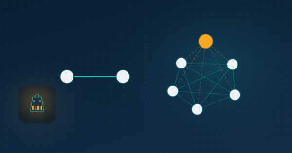
Hub-and-spoke (this guide): spokes only tunnel to the hub; B-to-C traffic routes through A.
- Fewer tunnels: N-1 for N sites, not one per pair
- Policy control centralized at the hub
- Adding a site = one new tunnel, to the hub only
Full mesh (every site tunnels to every other site) is worth the added complexity when:
- Spokes genuinely need to reach each other directly, not just the hub (see the Architecture note above)
- The hub would bottleneck high-bandwidth traffic between two spokes
- The hub being a single point of failure for inter-site connectivity is unacceptable
For key-card-scale traffic, hub-and-spoke is almost always sufficient.
FAQ: Multi-Site VPN on pfSense
Cheapest way to connect multiple business locations with a VPN?
Self-hosted, site-to-site WireGuard between pfSense (or similar) routers. Only recurring cost is internet + hardware already needed at each site.
Static IP required at every site?
No — only the hub. Spokes connect outward and need no discoverable address.
Does this support IPv6?
Yes, and IPv6 avoids the cross-site subnet-overlap problem IPv4 has, since each site's delegation is globally unique. AllowedIPs, routes, and firewall rules all need matching IPv4 and IPv6 entries.
What's the AllowedIPs difference between remote-access and site-to-site?
Remote access: one address per client. Site-to-site: the peer's entire LAN subnet (or specific hosts — see Step 3).
Can one pfSense box run both a site-to-site tunnel and a remote-access tunnel?
Yes — separate tunnel interfaces, separate keys. No conflict.
Can spokes reach each other directly, or only the hub?
Only the hub, by default. Each spoke's config in this guide routes to the hub's LAN only — spoke-to-spoke traffic isn't configured. If two spokes need direct reachability, either extend AllowedIPs/routes/firewall rules on both spokes to include each other's LAN, or use full mesh instead (see Scaling, above).
Handshake succeeds but no traffic passes — why?
Missing tunnel-interface firewall rule (Step 5), not a WAN or handshake problem.
What happens if the hub's internet goes down (hub-and-spoke)?
Every spoke loses connectivity to every other spoke — traffic between them routes through the hub. Main tradeoff against full mesh.
Related reading
- pfSense WireGuard IPv6 Setup: Full Tunnel and Split Tunnel Guide
- IPv6 Subnetting Guide: CIDR Prefixes & Usable Ranges
Recap
- Only the hub needs a static IP or DDNS — spokes need nothing
- Non-overlapping IPv4 LAN subnets at every site is mandatory; IPv6 mostly avoids this problem by design
- Transport subnet is dedicated, never carved from a site's LAN
- AllowedIPs on a site-to-site peer covers the whole remote LAN, or specific hosts for tighter scope
- Static routes: both directions, both protocols, every link
- WAN handshake rule: hub only. Tunnel-interface rule: every site, scoped to specific hosts/ports by default
- No NAT — real LAN addresses preserved end-to-end
- Hub-and-spoke by default; full mesh only when bandwidth or single-point-of-failure concerns justify the added complexity